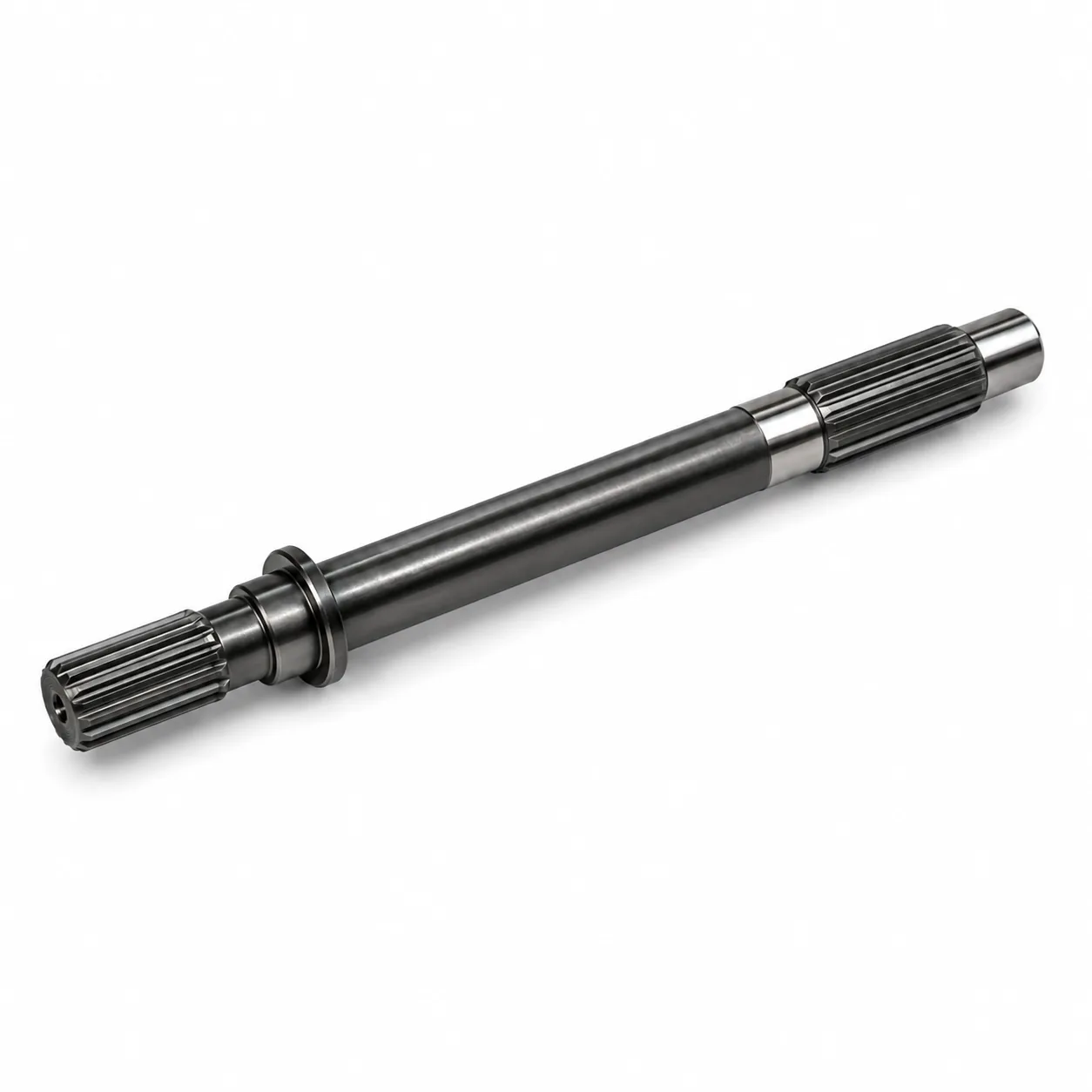
Custom Spline Shafts
Drawing-controlled external, internal and integrated shaft configurations.
View familyReliable spline shaft selection begins with the mating geometry rather than a generic diameter. The product range covers external splines, an internal spline configuration and an integrated gear-and-spline shaft, with available technical data presented alongside the drawing inputs needed to finalize geometry and fit.
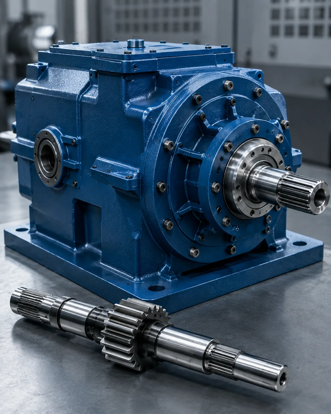
Browse by interface type first, then compare material, heat treatment and available geometry within each family.
Drawing-controlled external, internal and integrated shaft configurations.
View family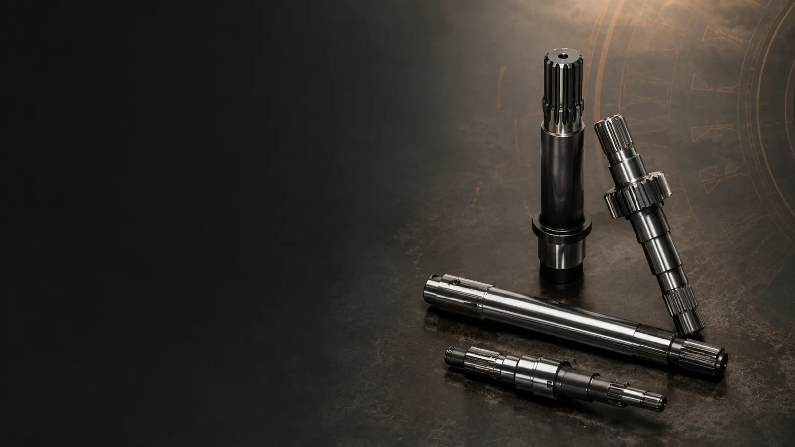
External tooth forms for mating hubs, gears and driveline interfaces.
View family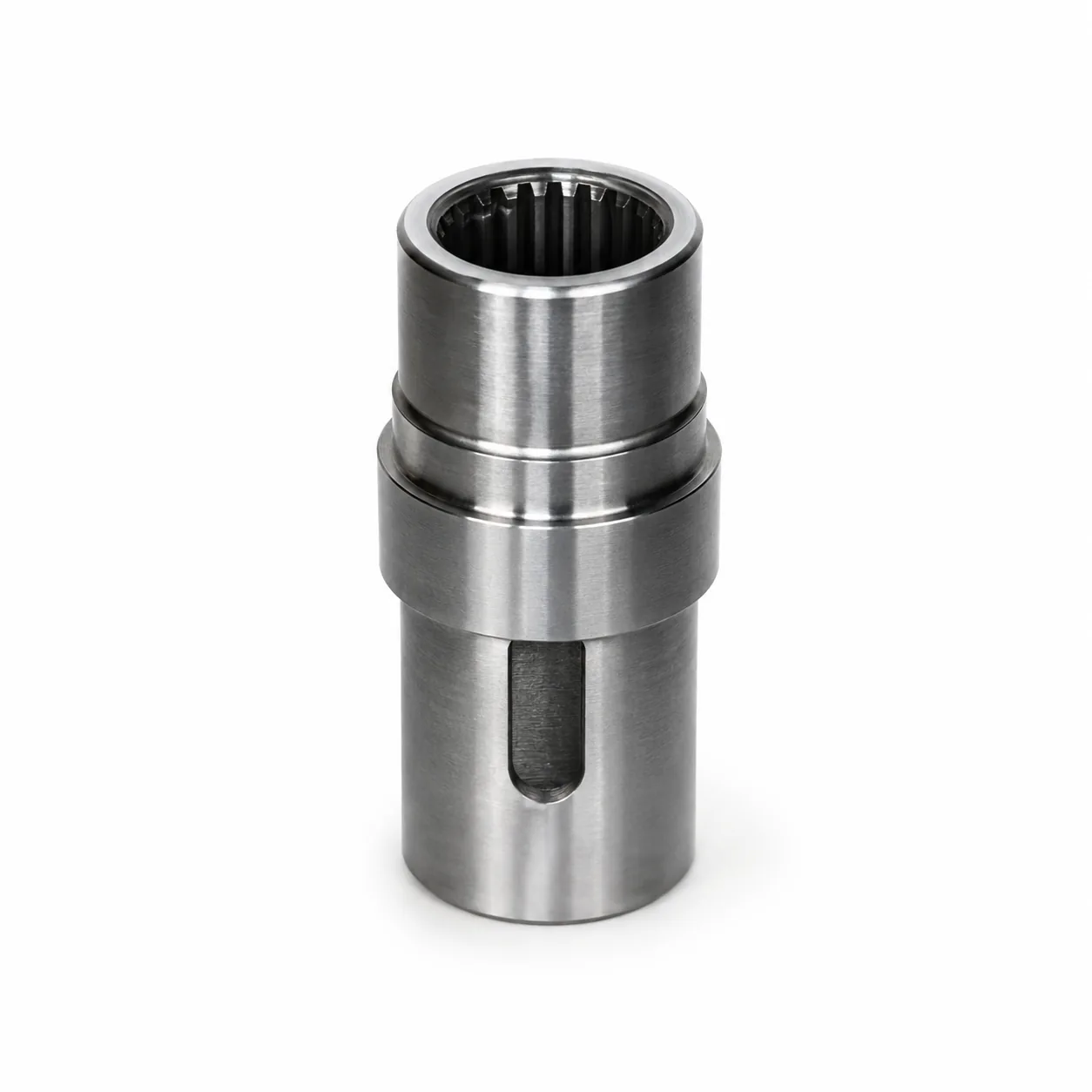
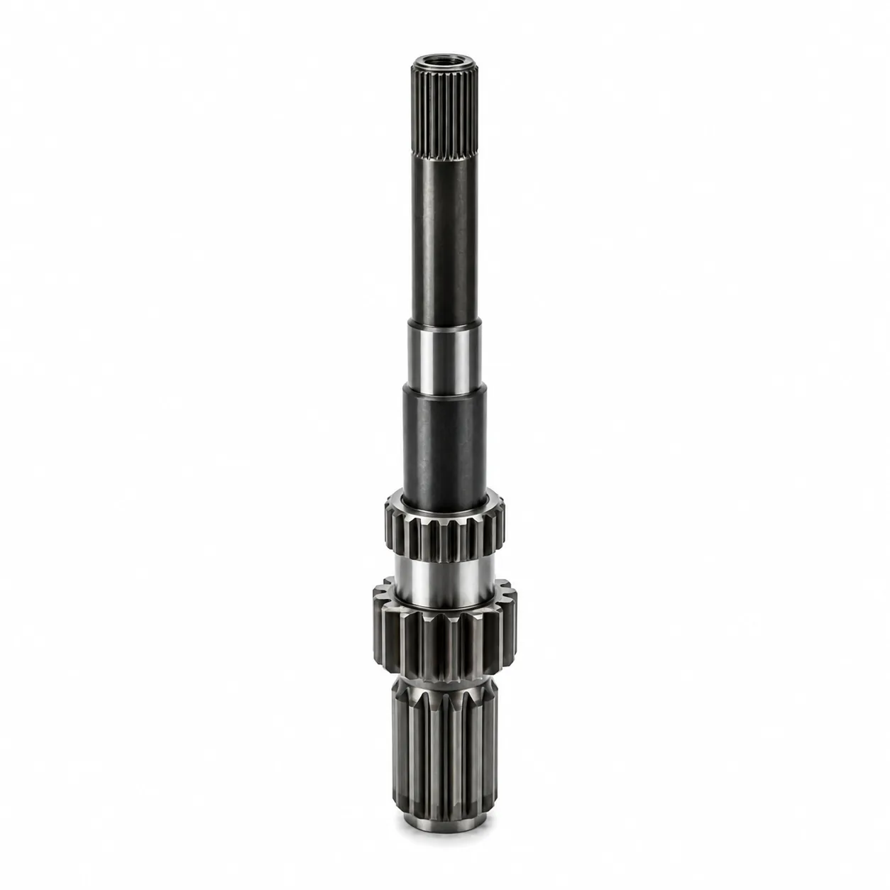
Integrated gear and spline features where multiple datums must work together.
View familyEach product page presents available specifications and the drawing inputs needed to complete a quotation.
C45 internal spline component, quenched and tempered to HB280-320 with Ra0.4 surface roughness specified for the configuration.
Integrated 18CrNiMo7-6 gear and spline shaft, 758 mm overall length, with M5 Z18 gear and M2.5 Z28 spline; carburized and quenched to HRC59-63.
M1.5 Z25 20CrMo external spline shaft with 30° pressure angle, carburized and quenched to HRC58-62 for agricultural machinery drive applications.
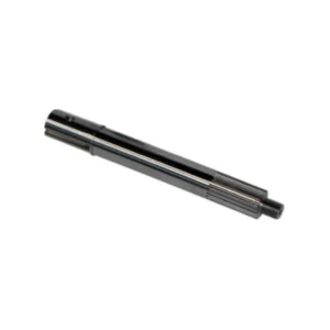
C45 external spline shaft with induction hardening to HRC55-60 for custom, drawing-defined power-transmission interfaces.
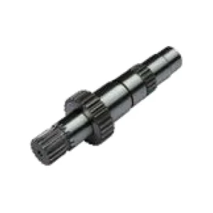
M2 Z30 external spline shaft in 20CrMo with 30° pressure angle, carburized and quenched to HRC58-62 for agricultural drive-shaft applications.
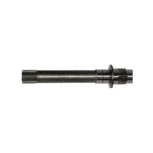
20CrMo M2 Z30 external spline shaft with 30° pressure angle, carburized and quenched to HRC58-62 for drawing-controlled agricultural transmission interfaces.
Agricultural drivetrains, gearbox connections and general transmission systems impose different shock, alignment, lubrication and service-access requirements.
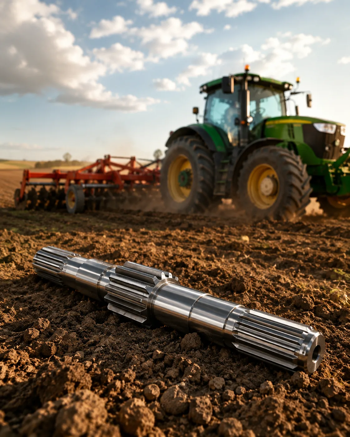
Check shock loading, contamination, service cycles and mating geometry before specifying the shaft.
Review concentricity, bearing-seat datums, lubrication and whether the spline is fixed or sliding.
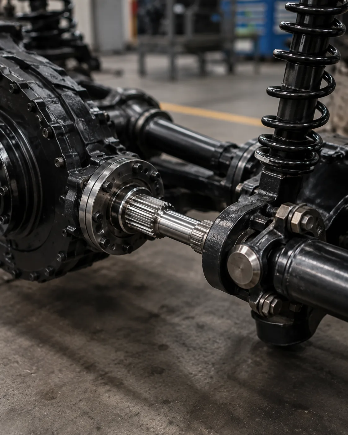
Define torque path, axial restraint, assembly access and inspection requirements across the connection.
Manufacturing routes are selected to match the drawing, material condition, hardness, geometry, inspection requirements and production quantity.
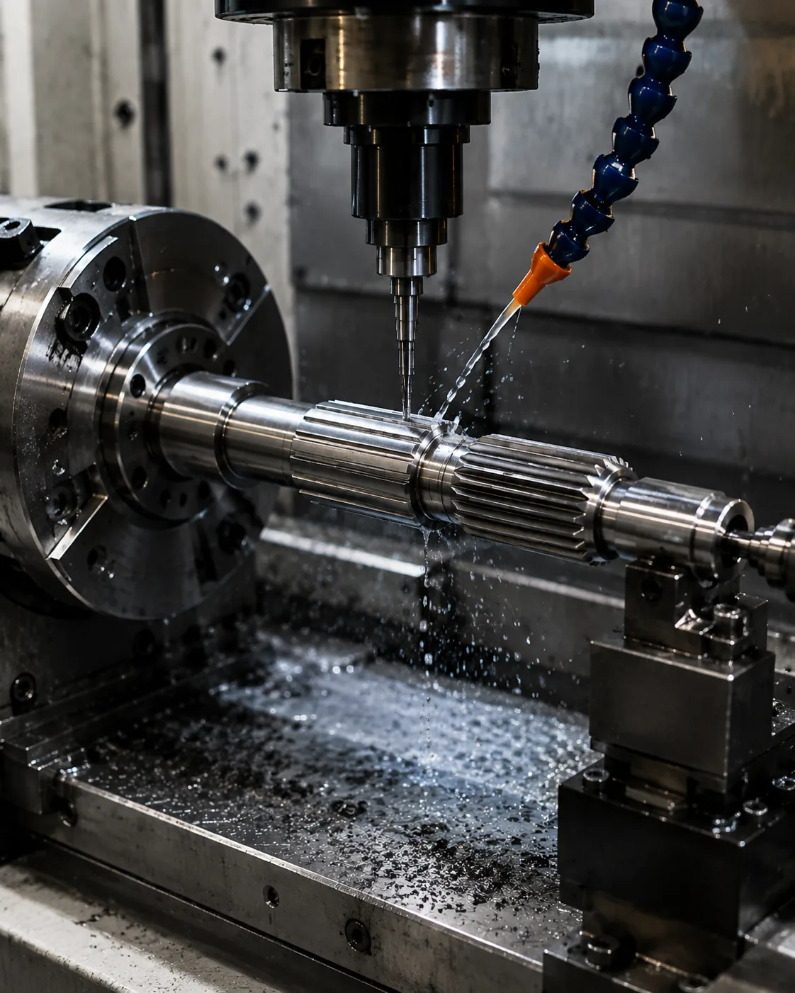
Establish reference surfaces and concentric features before the spline operation when the drawing requires them.
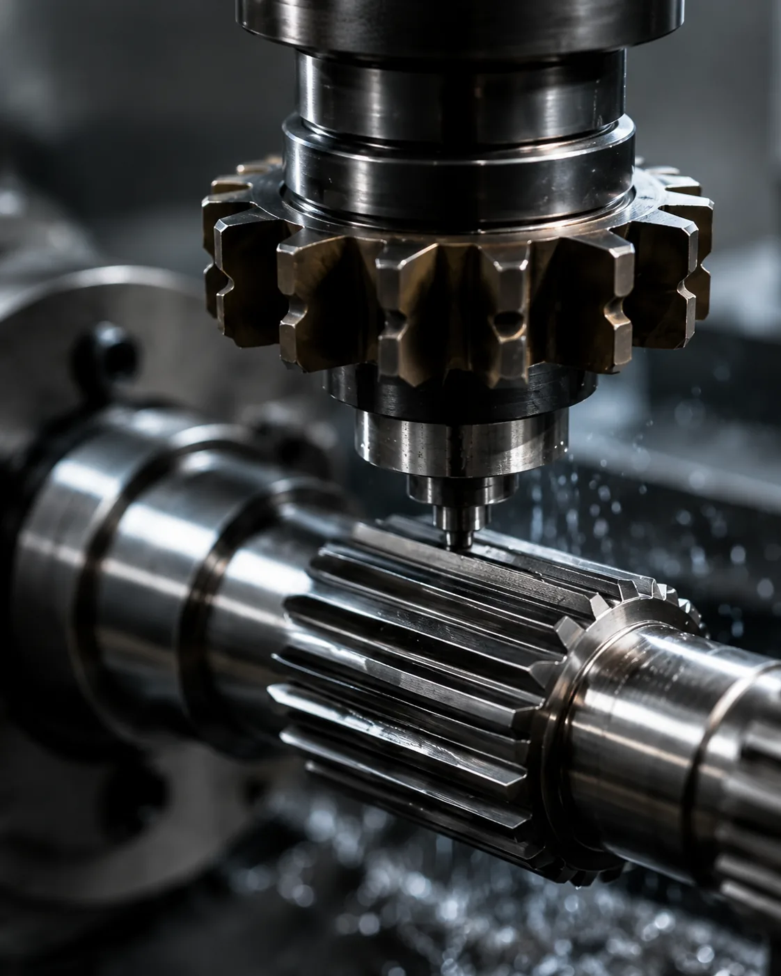
Milling, hobbing, shaping, broaching, rolling or grinding may be selected according to the actual tooth form and production route.
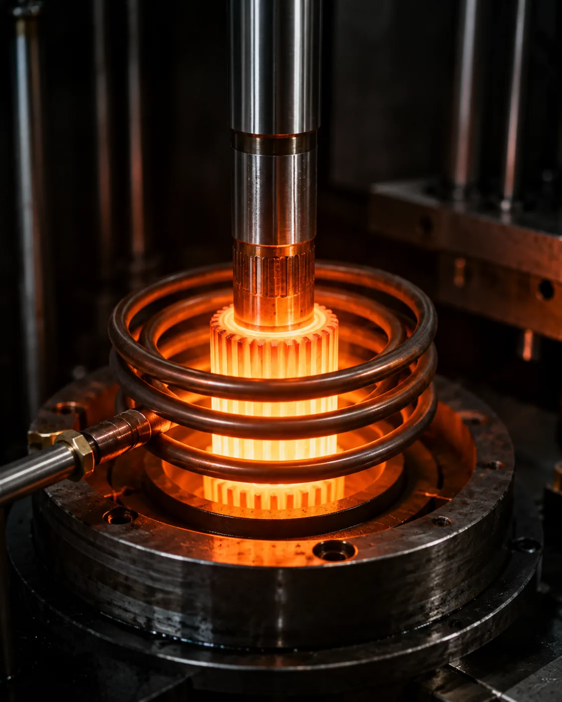
Sequence machining and heat treatment around distortion risk, hardness depth and final finishing requirements.
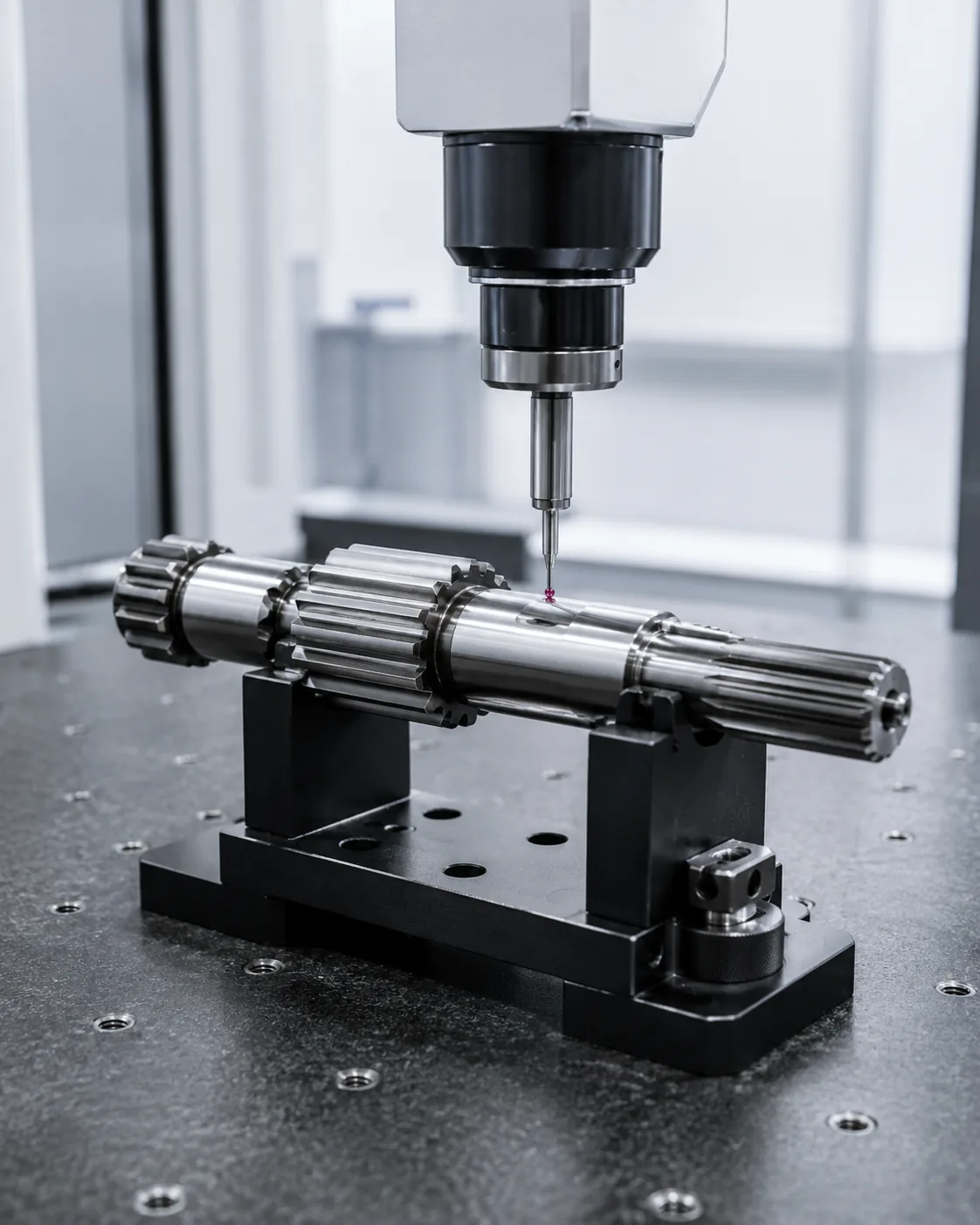
Verify the dimensions and relationships that determine assembly performance, not an isolated checklist.
A drawing is the best starting point. When a complete drawing is not available, provide the functional information below so open items can be identified instead of guessed.
Use the Knowledge Center when you need to define a new interface, interpret a drawing requirement or investigate wear before ordering a replacement.
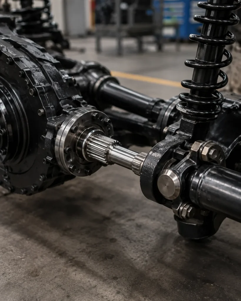
Lubrication Considerations for Sliding and Fixed Spline Connections — Sliding and fixed spline connections can have different lubrication needs because…
Read guide →Spline Tooth Pitting and Surface Damage: Inspection Guide — Pitting and surface distress should be documented before the parts are cleaned or discarded.…
Read guide →How Misalignment Damages Spline Teeth and Mating Hubs — Misalignment concentrates load toward tooth edges instead of distributing contact along the…
Read guide →Send the controlled drawing, material and heat-treatment requirement, mating details, duty information and inspection expectations. Open technical items can then be identified clearly before quotation.